UTC KA22427
LINEAR INTEGRATED CIRCUIT
UTC
UNISONIC TECHNOLOGIES CO., LTD.
1
QW-R110-002,A
I-CHIP AM/FM RADIO IC
DESCRIPTION
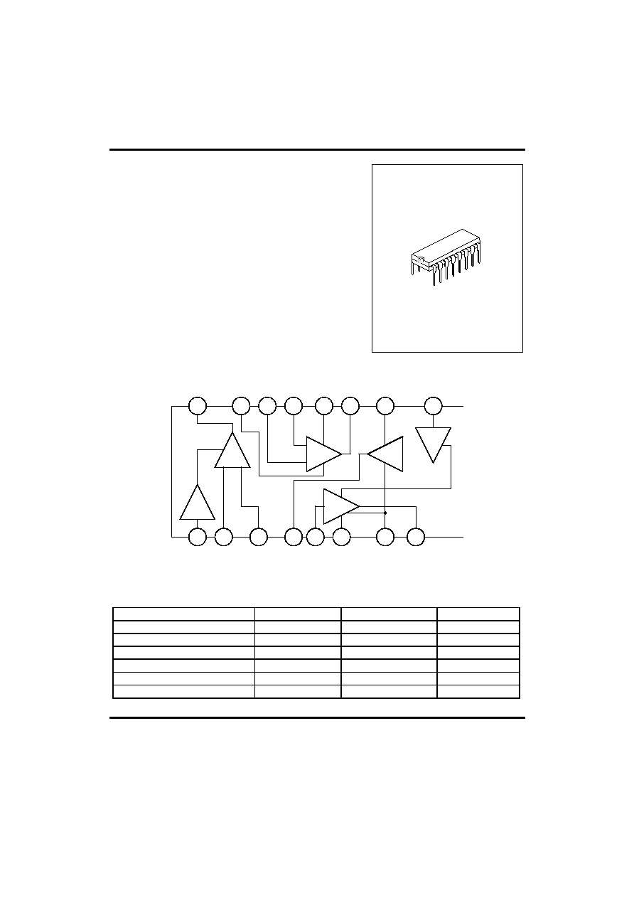
UTC KA22427 is a one-chip AM/FM radio integrated circuit
that is suitable for portable radio applications. It includes
AM amplifier, local OSC, AM mixer, AM/FM amplifier, AM
AGE, FM AGE circuit and also class b Audio Power Amplifier.
FEATURES
*Low external components count.
*Wide operating voltage : 3 - 13 V.
*Internal regulated supply for constant current operation.
*DC selection of AM/FM mode.
DIP-16
BLOCK DIAGRAM
4
3
2
1
16
15
14
11
13
12
10
9
8
7
6
5
AM local
OSC
AM HF IN
HF bypass
Audio
detector
out
Audio in
Ripple
Suppression
Audio GND
Audio power
out
AM IF OUT
HF GND
AM/FM IN
IF bypass
AGC
bypass
AM/FM
OUT
IF Detector IN
+Vcc
AM HF MIXER
AM LO
AM/FM IF
AM/FM
discriminato
Audio
amplifier
Regulator
ABSOLUTE MAXIMUM RATING
(Ta=25
∞C)
PARAMETER SYMBOL
VALUE UNIT
SUPPLY VOLTAGE
VCC
11
V
SUPPLY CURRENT
ICC
44
mA
POWER DISSIPATION
PD
600
mW
THERMAL RESISTANCE
RJ-A
100
∞C/W
OPERATING TEMPERATURE
TOPX
-18~65
∞C
STORAGE TEMPERATURE
TSTG
-40~125
∞C
NOTE:Ta>25
∞C, DERATE WITH 10mW/∞C UNLESS SPECIFIED.

UTC KA22427
LINEAR INTEGRATED CIRCUIT
UTC
UNISONIC TECHNOLOGIES CO., LTD.
2
QW-R110-002,A
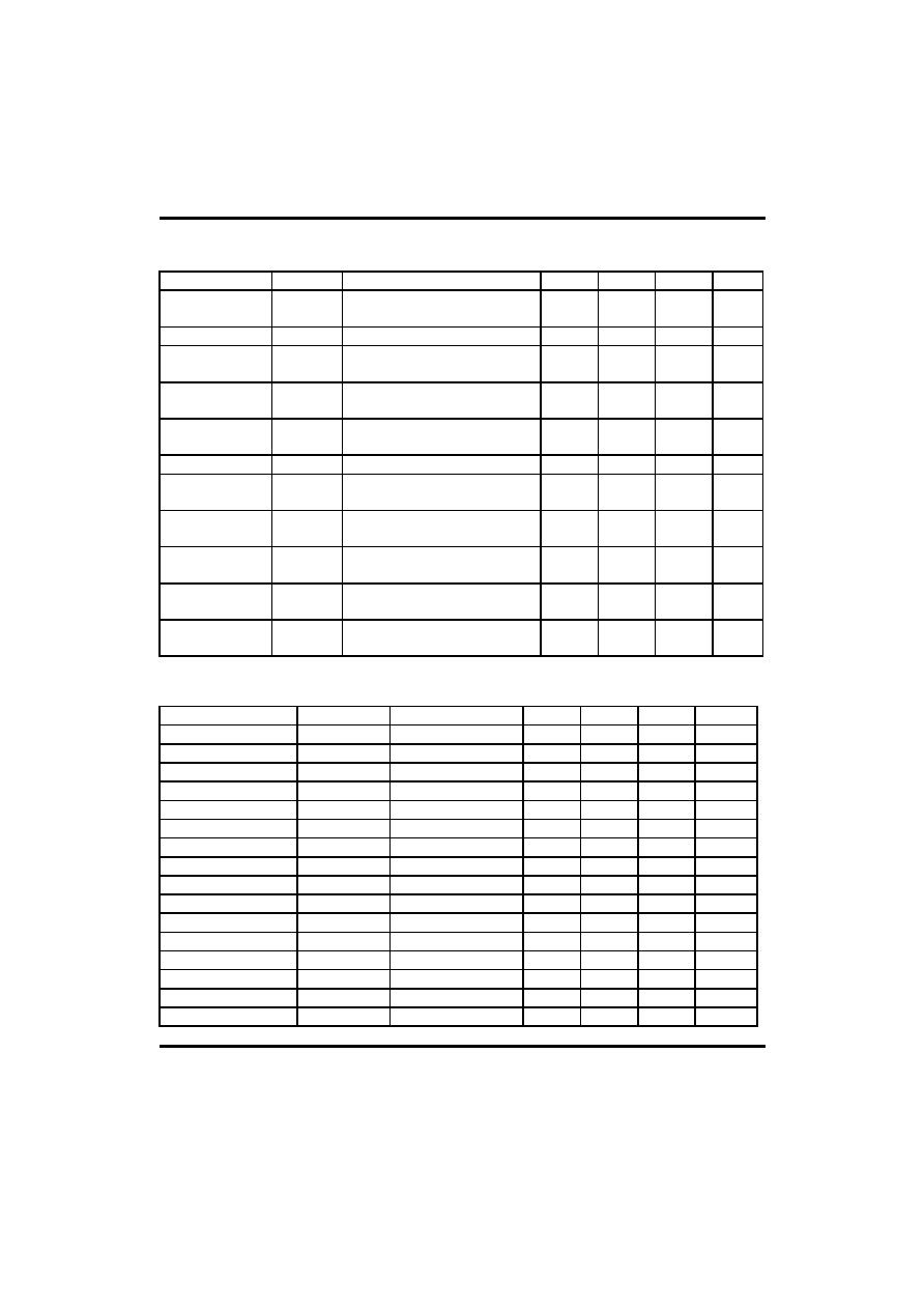
ELECTRICAL CHARACTERISTICS
PARAMETER SYMBOL
TEST
CONDITIONS
MIN TYP MAX UNIT
Quiescent Circuit
Current
ICCQ
SW1
FM,VCC=3V 7
12
17
mA
SW1
FM,VCC=9V
10 17 23
Pin 16 Terminal
Voltage
V16(FM) SW1
FM,ICC=42mA
2.0 2.4 3.1 V
Limiting Voltage
VIN(lim)
SW1
FM,VCC=5.5V,-3dB
V16=2.4V,VR=Min.
57
dB
µV
Internal Regulated
Voltage
VCC
SW1
AM,ICC=42mA
12.5 13.2 14.0
V
Pin 16 Voltage
V16(AM)
SW1
AM,VCC=9V 1.4
1.9
V
Signal to Noise
Ratio
VO SW1
AM,VCC=12V,VIN=37dB
SW2
45,V16=1.4V
1.5 3.0 V
Maximum Sensitivity
S/N
SW1
AM,VCC=5.5V,
SW2
8,VIN=37.5dB
15 20 dB
Power Output
POUT
SW2
8,VCC=5.5V,f=1KHZ
VR=Min. THD=10%
0.28
W
Total Harmonic
Distortion
THD SW2
45,ICC=42mA,f=1KHZ
VR=Min. VOUT=2V
0.5
4.0
%
Voltage Gain
GV
SW2
8,VCC=5.5V,f=1KHZ
VR=Min.
40
dB
INPUT - OUTPUT IMPEDANCE
(Ta=25
∞C,VCC=6V)
PARAMETER SYMBOL
TEST
CONDITIONS
MIN
TYP
MAX
UNIT
Pin 2 Input ( AM )
Rip2(AM)
f=465KHZ
200
K
Impedance ( AM )
Cip2(AM)
f=465KHZ
3
pF
Pin 2 Input ( FM )
Rip2(FM)
f=10.7MHZ
30
K
ImpedanceFM
Cip2(FM) f=10.7MHZ
3.5
pF
Pin 4 Output
Rop4
f=465KHZ
300
K
Impedance
Cop4
f=465KHZ
6 pF
Pin 6 Input
Rip6
f=1MHZ
50
K
Impedance
Cip6
f=1MHZ
5 pF
Pin 14 Input ( AM )
Rip14(AM)
f=465KHZ
300
K
ImpedanceAM
Cip14(AM) f=465KHZ
3.5
pF
Pin14 Input ( FM )
Rip14(FM)
f=10.7MHZ
300
K
ImpedanceFM
Cip14(FM) f=10.7MHZ 4 pF
Pin15 Output ( AM )
Rop15(AM)
f=465KHZ
300
K
ImpedanceAM
Cop15(AM) f=465KHZ
5.5
pF
Pin15 Output ( FM )
Rop15(FM)
f=10.7MHZ
300
K
ImpedanceFM
Cop15(FM) f=10.7MHZ 6 pF

UTC KA22427
LINEAR INTEGRATED CIRCUIT
UTC
UNISONIC TECHNOLOGIES CO., LTD.
3
QW-R110-002,A
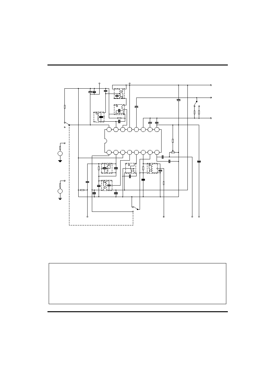
TEST CIRCUIT
1
2
3
4
5
6
7
8
16
15
14
13
12
11
10
9
1
2
3
4
6
1
2
3
4
6
1
2
3
4
6
1
2
3
4
6
1
2
3
4
6
1
2
3
4
6
1
2
3
4
6
~
~
FM
AM
SW1
AM HF
INPUT
V
OD
INPUT
GND
OUTPUT
Vcc
Icc
V13
V16
FM
AM
SW1
1.2k
Rg=50
Rg=600
HF
SIGNAL
AUDIO
SIGNAL
50
2pF
220pF
0.022
µF
0.022
µF
680pF
5k
51pF
0.047
µF
50
0.01
µF
0.022
µF
22k
0.001
µF
220
µ
F
3.3
µF
45
8
470
µF
470
µF
10pF
4.7k
220pF
0.047
µF
470
µ
F
SW2
FM IF
INOUT
UTC KA22427
UTC assumes no responsibility for equipment failures that result from using products at values that
exceed, even momentarily, rated values (such as maximum ratings, operating condition ranges, or
other parameters) listed in products specifications of any and all UTC products described or contained
herein. UTC products are not designed for use in life support appliances, devices or systems where
malfunction of these products can be reasonably expected to result in personal injury. Reproduction in
whole or in part is prohibited without the prior written consent of the copyright owner. The information
presented in this document does not form part of any quotation or contract, is believed to be accurate
and reliable and may be changed without notice.


